change_latency.c - measures ISR latency using a change notification interrupt
Measure latency using change notification. RB2 itself to generate an CN interrupt. Need to run this with a slow clock to avoid external loading effecting CN triggering point. Therefore, the macro
-DCLOCK_CONFIG=PRI_8MHzCrystal_4MHzFCY is defined to run the processor at 4 MHz. However, this means you must attach an external 8.0 MHz crystal for this to work. The image below shows the results of a scope capture on a dsPIC33E series processor, demonstrating a 9 us timing between rising edges, which is 36 Tcy (instruction) cycles. However, since this was measured using the bootloader, this includes an additional 2 cycles due to an additional goto instruction provided by the bootloader to jump to the remapped interrupt vector table.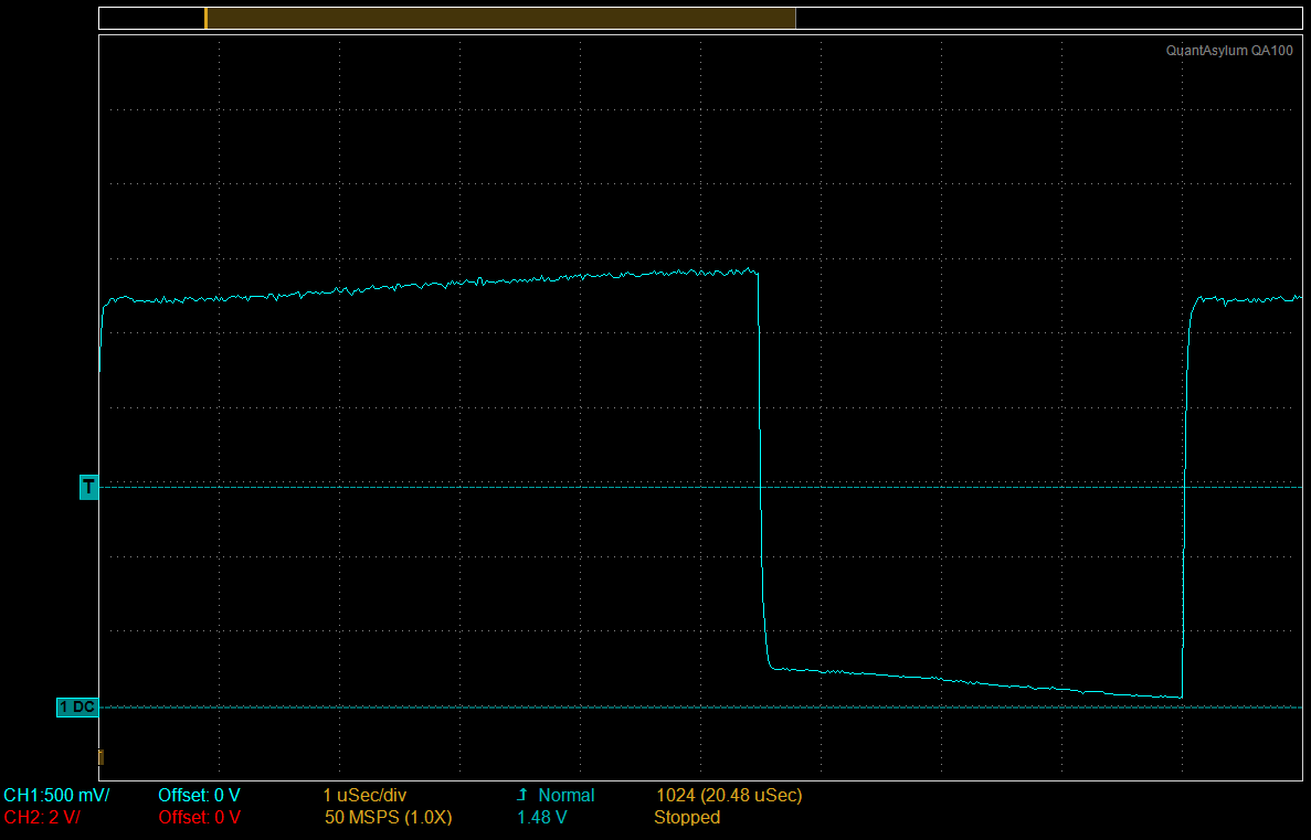
In addition, the high-speed baud rate (230,400 for all but PIC24F devices) doesn’t work in this mode. So, defining -DDEFAULT_BAURDRATE=19200 produces a usable baud rate.
#include "pic24_all.h"
Interrupt Service Routine for Change Notification. The compiles to the following 8 instructions (used xc-16 v. 1.11):
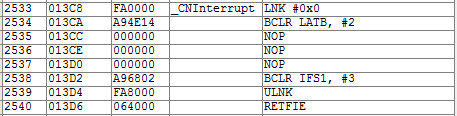
void _ISRFAST _CNInterrupt(void) {
Set output back to 0.
_LATB2 = 0;
Give the CN time to propagate so clearing the flag will actually clear it.
  NOP();
  NOP();
  NOP();
Clear the interrupt.
  _CNIF = 0;
}

int main(void) {
  configBasic(HELLO_MSG);
Configure IO pins.
  CONFIG_RB2_AS_DIG_OUTPUT();
  _LATB2 = 0;
  ENABLE_RB2_CN_INTERRUPT();
Configure Change Notification general interrupt.
  _CNIF = 0;         //Clear the interrupt flag
  _CNIP = 2;         //Choose a priority
  _CNIE = 1;         //enable the Change Notification general interrupt
This loop compiles to 4 instructions (using xc-16 v. 1.11):
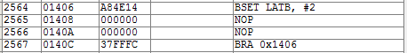
  while (1) {
    _LATB2 = 1;       //trigger interrupt by bringing high
    NOP();            //give the CN time to propagate
    NOP();
  }
}